Another broken spring bolt…

Our Oka has been left idle for the past couple of months since returning from our recent trek across the WA deserts.

But yesterday I removed one of the gas bottles for use at a Christmas BBQ and something around the rear spring looked a bit odd…

IMG_3536-2013-12-12-08-29.JPG-2013-12-12-18-59-2013-12-12-18-59.jpg

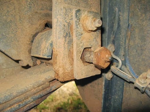
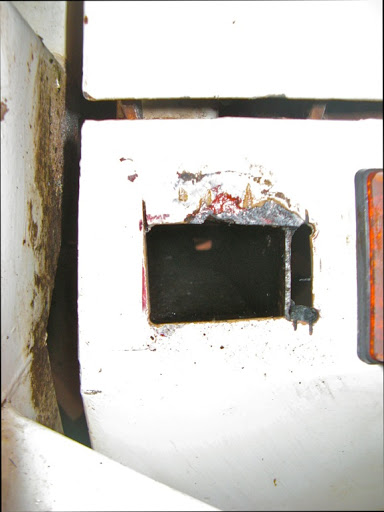
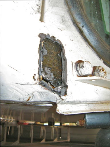
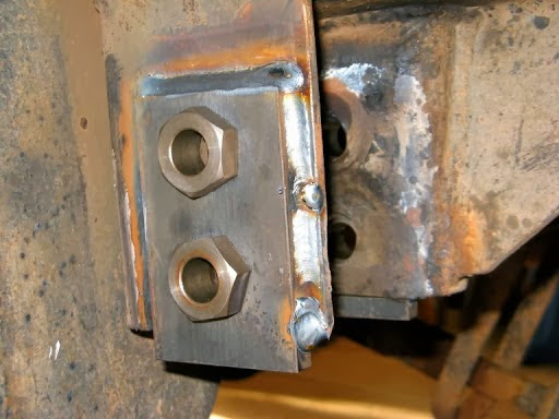
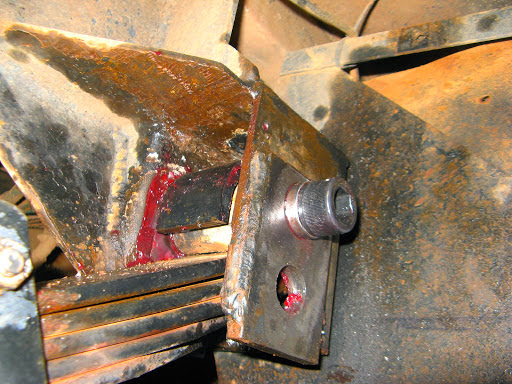
The rear suspension pin protrudes 50mm, which it shouldn’t

The spring bolt behind the gas bottle is protruding about 50mm whereas it should be flush with the chassis spring mount. The Nyloc nut on the inside of the bolt is still in place so it’s not rocket science to surmise that the bolt is broken in the middle, probably across the grease hole which would be its weakest point.

Gouges on the side of the gas bottle suggests that the broken bolt was being held in place by the bottle, which is probably better than the bolt falling completely out, but it may have been this way, unnoticed, for quite some time which is a bit of a worry.

The really strange thing about this event is not that a spring bolt has broken, we’ve experienced a few of those before, but that all spring and tyre related problems have always been on the same wheel, the drivers side rear. That now makes 3 spring bolts, 2 broken springs, a bogging and a tyre staking all on the same corner. What are the chances of that happening? I don’t believe there is anything very different about this corner, the construction and loading is very similar to the opposite side.

Replacing the bolt is not a major task, I have spares, it’s just a heavy job. The real questions are why and how to prevent future occurrences?

All other spring bolts apart from the 2 rears have been upgraded to 20mm diameter suspensions pins which are a lot stronger than the original 16mm bolts. These 2 rear bolts had previously been replaced by ultra-strong crankshaft quality 16mm bolts, running in bespoke replaceable bushes, and were claimed to be unbreakable, until now.

IMG_0917-2013-12-13-08-29.JPG-2013-12-12-18-59-2013-12-12-18-59.jpg

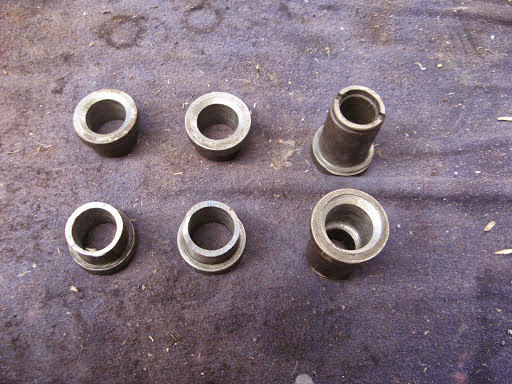
Replaceable screw in bushes for the previous 16mm rear suspension bolt upgrade

So I shall now upgrade the remaining 2 bolts to 20mm pins, which is not so easy (and the reason why they haven’t been done previously) since the chassis mounts were specifically designed for the replaceable bushes and I’ll have to redesign and reweld them to take 20mm pins. I was going to check and replace the urethane bushes anyway before our next trip.

I might consider going up market further to the 25mm suspension pins as fitted to the new NT model, (actually the NT pins are 1 inch or 25.4mm diameter). However more thought would be required since the spring eyes are not much more than 25mm anyway, actually around 32mm, which means the wall thickness of the urethane bushes can only be between 3-4mm (the NT pins actually run in steel/phosphor bronze bushes which are only 3mm thick).

The bolt replacement task is not a huge one and made all the better by the fault being discovered at home rather than on the side of some remote, hot, dusty, insect ridden track like previous similar events.

Here I have the time, facilities, shelter and materials access to do it at my leisure, all I need is the motivation but they don’t sell that at Bunnings, I know, I asked once which aisle it was in.

Since starting this article, I’ve replaced the rear suspension pins with high tensile 20mm bolts and fitted bushes to provide a larger surface area for their support.

IMG_4935-2013-12-12-18-59.JPG-2013-12-12-18-59.jpg

To do that I had to drill out the holes in both side plates to 25mm to accept the bushes, which would have been much easier if I had been able to turn the chassis on its side and use my large pedestal drill.

As it was I had to buy a new larger power drill and go up in size progressively from 20 to 25mm.

The bushes were fashioned from former Oka suspension bushes, cut to size and drilled out to 20mm to fit the new bolts. I also fitted new urethane bushes although the older softer versions weren’t as worn as I had expected.

IMG_4912-2013-12-12-18-59.JPG-2013-12-12-18-59.jpg

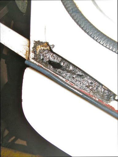
This is a simulation of the set up with bushes and thrust washers, and steel samples providing the side plates

(The previous broken bolt shown for size comparison)

IMG_4913-2013-12-12-18-59.JPG-2013-12-12-18-59.jpg

The former Oka bushes (R) were 1 inch external diameter but, allowing for some wear, reduced to 25mm quite well to fit the new holes, and when drilled out to 20mm leave adequate sidewall thickness

Because I could only get long enough Class 12.9 bolts in socket head versions I fitted a retaining and anti-rotation wire to their heads.

Drilling HT steel is not easy and the 3mm drill bit crackled as it went though. Smaller drill sizes just snapped. For good measure I also drilled the threaded end to accept an R pin so the nyloc nut can’t ever come off.

IMG_4942-2013-12-12-18-59.JPG-2013-12-12-18-59.jpg

While I had the opportunity, I changed from the lower to upper bolt hole position. This lowers the suspension by around 30mm and allows the airbags to take more of the load levelling task. It also tilts the differential yoke upwards slightly taking some stresses off the UJ.

All 12 suspension bolts/pins on our Oka are now 20mm HT steel so we should have no more failures of this kind.

Derusting the Oka

Rust holes can occur at several places on an Oka but mostly they are cosmetic and affect only the outer body skin and its support bars. Seldom will the main chassis rust badly.
I’ve found the best solution is to cut out the rusted metal, scape, brush or grind off as much surface rust as possible and coat with RANEX Rusbuster.
This converts the surface rust to an inert coating which can be directly painted RANEX is also good for just painting on to rust spots or rusty bolt heads.
I then cover the holes with thin white aluminium sheeting either glued, screwed or pop-riveted on.
Common rust areas are (sorry the photos are rotated 90º):

IMG_5882-2011-06-30-13-45.JPG-2012-11-13-08-30.jpg
Front side rust hole (both sides). The cross member is badly rusted.
IMG_5883-2011-06-30-13-45.JPG-2012-11-13-08-30.jpg
Rust hole where the windscreen meets the front scuttle.
IMG_5885-2011-06-30-13-45.JPG-2012-11-13-08-30.jpg
Rust hole where near the air filter

Clutch, from Michael Hession, Feb 2004

Clutch Problem – From Michael Hession, Feb 2004:
While we were away in Victoria, just after Christmas, we had to have our clutch replaced. The reason being, the Thrust Bearing failed and damaged the fingers of the clutch pressure plate. The bearing failed due to incorrect free-play adjustment. The clutch face was in good repair, but the pressure plate was unserviceable due to the damaged fingers. Two points that came out of this exercise were:

  1. Clutch Type
  2. Thrust Bearing Free-Play Adjustment.

1. Clutch Type
The standard clutch as fitted to all OKAs is a ceramic clutch and as OKA state in the owners manual, should not be slipped. If you do slip the clutch you will cause rapid wear to the clutch, pressure plate and flywheel. The ceramic clutch was fitted as early testing showed failure of an “organic” clutch. An organic clutch plate is what most people would recognise as a normal clutch plate.
It was recommended by Andrew Kee of Whitehorse Trucks (ex OKA dealers in Morwell, Victoria) that I replace my clutch with an organic type. He had supplied some ten of these to various OKA owners and had had no problems. The advantages being that the clutch can take some slip without undue wear or problems, and it is much softer on the drive-train giving a smoother take-up of the load.
The new NT OKA has an Organic Clutch. I have since learnt that Paul Nott is a good source. The clutch that was fitted to my vehicle is made by Daikin and if you go on their website you will find they have a listing for OKA (WA) and the part numbers start with OK.2. Thrust Bearing Free-Play Adjustment
Terry of Eastside Trucks, Morwell, carried out the repairs to my vehicle. He explained that it is a common problem, that he has found a lot of OKAs have the free play on their clutches incorrectly adjusted. Too often the thrust bearing is under load and therefore working (turning) continuously, leading to early failure of the thrust bearing, or at worst a slipping clutch.To ensure that it is adjusted correctly the following procedure needs to be followed:
        1.        Remove the inspection plate from the bottom of the bell housing (6 screws). Some vehicles will have a grease nipple for greasing the thrust bearing.
        2.        With the plate removed you will be able to see the side of the thrust bearing. With a long screw driver you should be able to freely rotate the bearing with the clutch disengaged.
        3.        If the bearing turns freely, all is good so far. Have someone operate the clutch pedal. As they slowly push the pedal down, you keep on turning the bearing until it stops. At this point the clutch pedal should have moved about 25mm; if so your free-play is adjusted correctly.
        4.        If the bearing does not turn freely, you either have a seized bearing or more likely not enough free play. You will need to adjust the free play by adjusting the adjustment bolt, which is on the opposite side of the bell housing to the clutch lever arm. N.B. Too much free-play will make it difficult to disengage the clutch.
        5.        You will need to test your setting to make sure you can still disengage the clutch.

Replacing the Rear Seal on the VE Injector Pump

Replacing the Rear Seal on the VE Injector Pump

Background

The injector pump on our Oka developed an annoying minor leak from the rear distributor head several years ago but recently it got suddenly worse and was losing around 200 ml each time it started or stopped, and dripped all the time in between. So it was Time Something Was Done.

The cause of the leak is hardening of the O-ring around the rear distributor head following the removal of sulphur from diesel fuel some 10 years ago. The sulphur acted as a lubricant keep the seals supple and its removal (on good environmental grounds) allowed seals to harden and leak.

b2187456-2012-04-7-08-37.jpg

The hardened (and brittle) O-ring which caused the leak

Removing the pump to replace the seal it is not a trivial job and it got more challenging the further I got into it, but I have now done it successfully and it required only a few spares, some fairly normal tools plus a few days of work.

No really tricky skills are required and anyone with reasonable car maintenance experience could do it. And unless there is something else seriously wrong with the pump, there is no need to go to the expense of a professional rebuild.

I got a lot of useful tips and support from my mate Dave in Perth who was a “transportologist” (truck driver) and has had a lot of experience of injector pumps and diesel engines, including an Oka. So finding someone who knows about injector pumps and/or Okas and can advise you is a well worthwhile. Internet resources may be relevant to the Bosch VE injector pump but they are not likely to be specific to the Perkins engine on an Oka.

Before starting, read all you can find about the VE pump from internet resources, especially the warnings about engine timing and how not to lose it, and ensure you have or can get the item listed below.

Note: If your pump does not have a shaft locking bolt like in the photo below, do a lot more research on engine timing before embarking on this process.

804e8146-2012-04-7-08-37.jpg

You’ll need to locate the shaft lock bolt and its wedge shaped spacer, shown here in the unlocked state

In preparation, you’ll need the following items:

      • A VE pump seal gasket/O-ring set (from a Bosch dealer or the internet using the correct part number of your pump)
      • A pump flange gasket (from a Perkins dealer)
      • Front pump gear cover gasket (from a Perkins dealer or gasket goo can be used)
      • A hydraulic pump O-ring or gasket (gasket goo can be used)
      • Oil filter/cooler mounting gaskets (2) (from a Perkins dealer. Must be new to prevent high pressure oil leaks)
      • Gasket goo (Loctite Blue Maxx)
      • Loctite 423 medium strength thread locker fluid
      • A bolt-on gear puller (needs to be fairly small to fit in the space below the water pump housing and use M8 bolts. I modified a harmonic balancer puller to suit)
      • A 13 mm deep ring spanner you are willing to modify (shorten)
      • Oil filter element (optional but preferable)
      • Fuel filter element (optional but preferable)
      • Digital camera to record the location of components (optional but preferable)
      • A mate like Dave (essential)

Action Plan to Remove the Pump

      • Remove the passengers seat and side engine access panel.
      • Thoroughly degrease and clean the side of the engine, pumps and fuel filter with degreaser.

8c140c71-2012-04-7-08-37.jpg

Access to the pump on our Oka is a bit tricky…

Take plenty of photos of the location of pipes, bolts and cables to aid subsequent reassembly.

      • Move any cables and water pipes aside and hold with tie wraps to provide easier access to the pump area.
      • Mark the top of the pump front cover on the timing case below the water pump housing (for ease of reassembly since it’s asymmetric) and remove the cover.
      • Loosen the drive shaft nut far enough to see the keyway (using a mirror) and ensure that it is pointing upwards. (Note: avoid dropping the nut or lock washer down the front of the timing case. Stuff a rag down there and use a magnetic wand). Put the nut back on if you have to turn the engine to make the keyway upright. It was tightened to 58 ft-lbs.

file-2012-04-7-08-37.jpg

The keyway should be as vertical as practical

      • Disconnect the starter battery to prevent the engine from being turned any more.
      • Lock the pump drive shaft by removing the wedge shaped spacer bar (it has a slot rather than a bolt hole so it can fall out as soon as the bolt is loose), tighten the locking bolt and secure the spacer to the pump throttle lever with wire to remind you to unlock the shaft after reassembly. (Note. Do not turn the engine with this locking bolt engaged, you will damage the pump).
      • Important Note: If your pump does not have a shaft locking bolt, you will need to use a more complex process for ensuring that engine timing is not disturbed and you will need to do more research before embarking on this task.]

d9a21c81-2012-04-7-08-37.jpg

The shaft is now locked and the spacer safely stored away, wired to the throttle lever so it can’t easily be forgotten

      • Mark the fuel direction on the 2 fuel filter pipes from the lift pump and the return to the tank using sticky tape to avoid later confusion.
      • Remove the fuel pipes between the filter and injector pump.
      • Remove the remaining fuel pipes from the top of the injector pump.
      • Remove the fuel filter and bowl behind the pump.
      • Release the throttle cable end from the pump lever.

df21004f-2012-04-7-08-37.jpg

The fuel filter is out but there’s still a long way to go

      • Drain the radiator water but…
      • 167d27de-2012-04-7-08-37.jpg
      • …don’t knock your bucket over
      • Remove the water pipes from the thermostat housing and rear engine block to the oil cooler. This improves side access and allows the oil cooler to be removed later.
      • Remove the high pressure fuel lines from the rear of the injector pump and the injectors on the engine and put aside so that no dirt can enter the pipes.
      • Cover the exposed ports on the injectors and the rear of the pump with tape or screw caps (eg chair tips) to avoid dirt falling in.
      • If there aren’t any timing marks, scribe some on the flange of the injector pump and the timing case to use later as confirmation of correct reassembly.

d95dd855-2012-04-7-08-37.jpg

Scribe timing marks on timing case (this needs one on the flange too)

(Photo courtesy of Mike’s 1993 Dodge Cummins Truck Blog).

      • Remove the front drive shaft nut (22 mm socket) and lock washer, being careful not to allow them to drop into the timing case (stuff a cloth between the front of the gear and the timing case and use a magnetic wand). The nut is tightened to 58 ft-lbs.
      • Access to 2 of the 3 pump flange nuts is very difficult, particularly the lower nut which will probably require the hydraulic pump to be withdrawn and moved aside for access (however it’s not necessary to remove any hydraulic pipes).

9bb6e388-2012-04-7-08-37.jpg

The lower flange bolt is actually more difficult to access than it looks

      • Access to the top bolt holding the hydraulic pump on is also very difficult as it is partly hidden below the injector pump and it’s easier if the oil filter/cooler mounting is also removed first. You may need to make up a special tool to remove this bolt as it comes very close to the bottom of the injector pump as its being undone and ring spanner can no longer be used. (If you are lucky someone will have replaced the top bolt with a socket head bolt, as I have now, so that a long Allen key can be used from the rear). My top bolt has a slot cut in it for a screw driver but I didn’t realise what it was for until I had removed it.

24489cfa-2012-04-7-08-37.jpg

Don’t attempt to remove the nearby socket head bolts, they hold the spline bearing case on to the timing case

      • The hydraulic pump will need to be twisted sideways while being withdrawn (and when being replaced) as its top flange will strike the bottom of the injector pump before the splined shaft has cleared the drive gear. You may also have to release the proportioning valve from the front chassis to provide sufficient slack for the hydraulic pipes.
      • Push the pump downwards and out of the way but don’t damage the splines on the engine mount. 
      • Cover the gear opening to avoid dirt falling in.
      • The injector pump is now more accessible.
      • Loosen the top 2 flange nuts most of the way so that when the pump is pushed back it can’t fall off the studs.
      • Remove the lower flange nut. This is the most difficult nut to access of the whole job. It is recessed and difficult to fit a socket on and might require a special tool made up to remove it. I shortened the handle of a deeply offset 13mm ring spanner, since there is limited room to rotate a full length spanner.
      • Whilst it didn’t happen to me, others have experienced the studs coming out of the timing case instead of the nuts unscrewing. In this case they will need to be reinserted minus the nuts and tightened before reassembly.
      • Remove the nut and bolt holding the rear support plate of the pump to the bracket on the engine block. (Note, this is very easily overlooked, as I found).

58c326e2-2012-04-7-08-37.jpg

This bolt is very easy to overlook

4e3916e4-2012-04-7-08-37.jpg

A bolt on gear puller modified to fit under the water pump housing and uses 2 x M8 bolts for attachment to the drive gear

      • Using a bolt-on gear puller, push the pump shaft out of the drive gear. (Do not use a gear puller hooked against the timing case, it will break the case. There are 2 M8 bolt holes in the drive gear for a bolt-on puller.) The drive shaft is tapered and can be very difficult to dislodge. Apply tension to the puller and then give the centre bolt a sharp tap with a mallet to break the joint.
  • Remove the remaining flange nuts and carefully withdraw the injector pump from the rear, ensuring that the woodruff key does not fall out (use a magnetic wand as soon as it’s visible).
  • 88f2916a-2012-04-7-08-37.jpg

    The small woodruff key on the magnetic wand

        • The injector pump is bigger and heavier than it looks (around 6-7 kg) so provide support to ensure that it can’t fall over, or fall off the work bench.

    3dfedba1-2012-04-7-08-37.jpg

    The pump is off, cleaned ready for work

        • Protect the drive shaft threads with a rubber chair tip.
        • After removing the injector pump, the drive gear may appear to have moved. It can roll sideways on the gear teeth but should stay in mesh. Don’t be tempted to relocate it manually, you might loose the engine timing. It can be recentred during refitting of the pump.

    3cb83881-2012-04-7-08-37.jpg

    The drive gear has rolled sideways but will stay meshed. Don’t move it manually

    Resealing the Pump

        • There are a number of internet resources available which describe how to replace the rear O-ring seal on the VE pump, especially this one at http://www.crustycrank.com/resealinjpump.htm#injpump. All of them emphasise that the pump should be held vertically downwards with the distributor head pointing upwards so that as the head is released, no internal parts can drop out of their correct position.
        • I clamped my pump in a small wooden bench vice mounted on top of the workbench for ease of access. Use wooden blocks to avoid damage to the pump when clamped.

    6aace661-2012-04-7-08-37.jpg

    The pump secured vertically in a bench vice

        • Remove the rear support plate on the pump. This is held on (in my case) by a combination of Torx and Allen headed bolts which can be quite tight so avoid damaging the heads during this process. I didn’t need any additional help to remove them but if they won’t loosen easily, a suggestion is to use a a pipe or G clamp to hold the Torx/Allen bit tightly into the bolt head and turn it with a spanner.

    0b1bd1b4-2012-04-7-08-37.jpg

    A clamping method for removing stubborn Torx or Allen headed screws (photo courtesy of crustycrank.com)

        • One of the bolts holding the rear support plate on is also one of the 4 bolts securing the distributor head. Replace that bolt after removing the plate.
        • Remove the fuel cut off solenoid from the distributor head and carefully remove the plunger and its spring.

    d853314a-2012-04-7-08-37.jpg

    The distributor head covered in smooth tape

        • To access the O-ring, the distributor head must be partly (but NOT completely) released.
        • Undo the 4 bolts progressively until you can see the head moving upwards (depending on the position in its cycle when it last stopped, the head may be spring loaded and come up by itself).

    121f5588-2012-04-7-08-37.jpg

    The head only needs to be removed this far

        • Continue to undo the 4 bolts progressively, ensuring that the head is coming up with them, until the O-ring can just be seen but no more. The head may need to be lifted gently to ensure this but don’t allow the head to come completely out. It may not cause any problems but why take the risk?
        • Remove 2 diagonally opposite bolts leaving 2 bolts holding the head in place.
        • Carefully lift and cut the O-ring and remove it but don’t scratch the groove that it sits in. I used a wooden cocktail stick but the O-ring was hard and brittle (which was the cause of the leak) and broke easily.

    98978132-2012-04-7-08-37.jpg

    Replacing the O-ring (photo courtesy of crustycrank.com)

        • Clean the O-ring groove as well as possible.
        • Now the new O-ring can be fitted.
        • Wind some smooth tape around the rough exterior of the distributor head so that the new O-ring is not damaged during fitting, but don’t cover up the bolt heads or holes, access will be needed.
        • Grease the outside of the tape and the new O-ring well and stretch it over the distributor head.
        • Slide the O-ring down until it drops into the gap and carefully manoeuvre it into its groove on 2 sides. It will still be on the outside of the 2 bolts.
        • Reinsert the 2 bolts which were removed so that they hold the head in the same position, being careful not to damage the O-ring on the way.
        • Holding the O-ring away from the threads (I used a cocktail stick), remove the first 2 bolts one at a time and allow the O-ring to slip into the groove.
        • Once the O-ring is fully in its groove, tighten all 4 bolts progressively so the head slides evenly back into its location.
        • Refit the rear support plate.
        • Reinstall the fuel cut off solenoid with the plunger and spring.
        • If no other work is required on the pump, the resealing task is complete and it can be refitted to the Oka by reversing the above process.

    a734dd38-2012-04-7-08-37.jpg

    The injector pump complete and ready for refitting

    Flushing out the Pump (Optional)

        • In my case I also wanted to flush out the inside of the pump since I had previously replaced the throttle shaft and its bush and seal, and wanted to remove any lingering swarf and dirt that may have been left in the pump body from that process. Since I did that job without removing the pump, I could not easily flush it out at the time.
          • To do this you will also need a rectangular top cover gasket which probably came with the gasket/O-ring set.
          • Removing the top cover is fairly straightforward but the throttle linkage inside needs to be removed carefully. It is also a bit tricky to replace when putting the cover back on and this blog entry explains how to do that.
          • I used the lift pump lever to pump some clean filtered diesel into a container to flush out the pump and then refilled the pump with clean diesel before refitting the top cover to make subsequent priming of the system a bit easier.
          • While it was empty, I also checked inside to ensure that no components had moved or fallen out during the resealing process.

    748b4baa-2012-04-7-08-37.jpg

    Checking the internals of the pump

    Reassembly Notes

        • Use Loctite on all major bolts and nuts, as in my case none of them had spring washers or nyloc nuts and you don’t want these critical parts to come loose.
        • Clean everything well before reassembly, especially oil passages where dirt or bits of hardened gasket may have lodged.
        • Refit the hydraulic pump by twisting it sideways while holding the splines level to mate with the drive gear. Use a M8 socket head screw in the top bolt hole and a long Allen key to tighten it from the rear.

    a05f77a2-2012-04-7-08-37.jpg

    The hydraulic pump refitted with a socket head screw

        • I replaced the oil filter element since it need one anyway and the oil filter mounting was easier to replace without the filter attached. In my case the block on the side of the engine did not detach so I didn’t need to replace its gasket.

    3f853772-2012-04-7-08-37.jpg

    Oil filter/cooler mounting refitted

        • I also replaced the element in the fuel filter and cleaned out the bowl while it was out.
        • When refitting the injector pump, ensure that the woodruff key is well seated in its slot and can’t easily get knocked out.
        • To re-centre the pump drive gear, insert an M8 bolt into the front of the gear and using a rubber strap, gently pull and secure the gear across the engine so that the centre hole is approximately central in the opening and the keyway is upright. The tapered shaft on the pump will then automatically centre it correctly.
        • Check that the timing marks scribed earlier still line up before tightening the flange nuts.
        • Double check that the shaft lock bolt on the injector pump has been reset and the spacer refitted before attempting to turn the engine.
        • Torque the drive shaft nut, with a new lock washer, to 58 ft-lbs. I also checked visually that the woodruff key was actually in the slot before finally tightening the nut.
        • Note that the pump drive gear cover is asymmetric and only fits one way round.

    Priming the System

        • Loosen the banjo nut on top of the fuel filter and use the priming lever on the lift pump to fill the bowl until fuel comes out of the banjo nut, then retighten it.
        • If you are replacing the oil filter, refill the element with around a litre of oil before refitting it, to aid the re-priming of the oil system.
        • Switch off or disconnect the lead to the fuel cut off solenoid on the injector pump and spin the engine until the oil pressure comes up before actually starting the engine (a good idea even if you haven’t just resealed the injector pump.
        • Don’t forget to refill the radiator and check for water leaks.

    Testing the System

    b804606e-2012-04-7-08-37.jpg

    Everything back in place ready for testing

        • Loosen the injector nozzle nuts on cylinders 2 and 3 slightly to allow air trapped in the injector pump to be cleared after the engine first starts. A mist of diesel will squirt out so keep clear of the injectors. After about 10 seconds, stop the engine and tighten the nuts.
        • My engine fired immediately and ran fairly smoothly during this process but ran very smoothly after tightening the injector nozzles.
        • If for any reason something goes wrong and the engine over revs, there is a mechanical “stop engine” lever on the side of the pump.

    7d16e917-2012-04-7-08-37.jpg

    Mechanical Engine Stop Lever

        • Subsequent test runs showed no signs of the original fuel leak.
        • Recheck the water level after a few test runs and the task is complete.

    Post Completion Note:


    About 2 weeks after the rear seal was replaced, a quite severe leak developed around the top cover of the pump. This was very annoying, meaning that the top cover had to be removed again. The cause was found to be an undersized o-ring seal around the top cover. 

    • 01671c26-2012-04-7-08-37.jpg
  • On the left, the seal which leaked after 2 weeks. Note that is is much thinner than the new seal on the right.
  • How this came to be in my overhaul kit remains a mystery as it’s the same shape as the original, and the new seals, but was much thinner, accounting for the leak.

    b733069e-2012-04-7-08-37.jpg

    The thinner, leaking seal is in the centre and the others are full size seals

    When replacing the top cover seal, ensure that you have the correct size for your pump to avoid an unnecessary secondary rebuild. It’s much more difficult replacing the top cover seal with the pump attached to the engine than on the bench. See here for how it can be done.


    If this leak had occurred after leaving for a long outback trip it would have been extremely frustrating.

    While the top cover was off, I also replaced the Stop Lever seal and the throttle shaft seal.

    I found MTQ Diesels in Adelaide very useful for the supply of Bosch seals and overhaul kits, and quite economical. The Bosch part numbers are:

    1. Repair seal kit, 1 467 010 059, $22.00. This contains all the rubber seals, copper washers and screw caps to overhaul the pump (but no instructions). If you need to replace the throttle shaft and its press-in bush due to wear, order those items separately.
    2. Top cover o-ring seal, 1 461 015 302, $4.00. I bought a spare top cover o-ring seal in addition to the one in the kit.

    Epilogue:

    I completed the above resealing of the injector pump in April 2012.

    During June to September we did a 13,000km trek across the desert tracks of WA, NT and SA (see here for details) and I’m pleased to say we had no leaks from the injector pump and engine performance was at least as good as before and maybe a bit better at the top end.

    The fully loaded Oka would cruise at 90kph when required whereas previously it wasn’t very happy above 80kph.

    Overall fuel consumption was a tick over 6.5km/l.

    David Ribbans, April 2012


    Replacing the Rear Seal on the VE Injector Pump

    Replacing the Rear Seal on the VE Injector Pump
    Background
    The injector pump on our Oka developed an annoying minor leak from the rear distributor head several years ago but recently it got suddenly worse and was losing around 200 ml each time it started or stopped, and dripped all the time in between. So it was Time Something Was Done.
    The cause of the leak is hardening of the O-ring around the rear distributor head following the removal of sulphur from diesel fuel some 10 years ago. The sulphur acted as a lubricant keep the seals supple and its removal (on good environmental grounds) allowed seals to harden and leak.
    The hardened (and brittle) O-ring which caused the leak

    Removing the pump to replace the seal it is not a trivial job and it got more challenging the further I got into it, but I have now done it successfully and it required only a few spares, some fairly normal tools plus a few days of work.

    No really tricky skills are required and anyone with reasonable car maintenance experience could do it. And unless there is something else seriously wrong with the pump, there is no need to go to the expense of a professional rebuild.
    I got a lot of useful tips and support from my mate Dave in Perth who was a “transportologist” (truck driver) and has had a lot of experience of injector pumps and diesel engines, including an Oka. So finding someone who knows about injector pumps and/or Okas and can advise you is a well worthwhile. Internet resources may be relevant to the Bosch VE injector pump but they are not likely to be specific to the Perkins engine on an Oka.
    Before starting, read all you can find about the VE pump from internet resources, especially the warnings about engine timing and how not to lose it, and ensure you have or can get the item listed below.
    Note: If your pump does not have a shaft locking bolt like in the photo below, do a lot more research on engine timing before embarking on this process.

    You’ll need to locate the shaft lock bolt and its wedge shaped spacer, shown here in the unlocked state
    In preparation, you’ll need the following items:
        • A VE pump seal gasket/O-ring set (from a Bosch dealer or the internet using the correct part number of your pump)
        • A pump flange gasket (from a Perkins dealer)
        • Front pump gear cover gasket (from a Perkins dealer or gasket goo can be used)
        • A hydraulic pump O-ring or gasket (gasket goo can be used)
        • Oil filter/cooler mounting gaskets (2) (from a Perkins dealer. Must be new to prevent high pressure oil leaks)
        • Gasket goo (Loctite Blue Maxx)
        • Loctite 423 medium strength thread locker fluid
        • A bolt-on gear puller (needs to be fairly small to fit in the space below the water pump housing and use M8 bolts. I modified a harmonic balancer puller to suit)
        • A 13 mm deep ring spanner you are willing to modify (shorten)
        • Oil filter element (optional but preferable)
        • Fuel filter element (optional but preferable)
        • Digital camera to record the location of components (optional but preferable)
        • A mate like Dave (essential)
    Action Plan to Remove the Pump
        • Remove the passengers seat and side engine access panel.
        • Thoroughly degrease and clean the side of the engine, pumps and fuel filter with degreaser.
    Access to the pump on our Oka is a bit tricky…
    Take plenty of photos of the location of pipes, bolts and cables to aid subsequent reassembly.
        • Move any cables and water pipes aside and hold with tie wraps to provide easier access to the pump area.
        • Mark the top of the pump front cover on the timing case below the water pump housing (for ease of reassembly since it’s asymmetric) and remove the cover.
        • Loosen the drive shaft nut far enough to see the keyway (using a mirror) and ensure that it is pointing upwards. (Note: avoid dropping the nut or lock washer down the front of the timing case. Stuff a rag down there and use a magnetic wand). Put the nut back on if you have to turn the engine to make the keyway upright. It was tightened to 58 ft-lbs.

    The keyway should be as vertical as practical

        • Disconnect the starter battery to prevent the engine from being turned any more.
        • Lock the pump drive shaft by removing the wedge shaped spacer bar (it has a slot rather than a bolt hole so it can fall out as soon as the bolt is loose), tighten the locking bolt and secure the spacer to the pump throttle lever with wire to remind you to unlock the shaft after reassembly. (Note. Do not turn the engine with this locking bolt engaged, you will damage the pump).
        • Important Note: If your pump does not have a shaft locking bolt, you will need to use a more complex process for ensuring that engine timing is not disturbed and you will need to do more research before embarking on this task.]
    The shaft is now locked and the spacer safely stored away, wired to the throttle lever so it can’t easily be forgotten
        • Mark the fuel direction on the 2 fuel filter pipes from the lift pump and the return to the tank using sticky tape to avoid later confusion.
        • Remove the fuel pipes between the filter and injector pump.
        • Remove the remaining fuel pipes from the top of the injector pump.
        • Remove the fuel filter and bowl behind the pump.
        • Release the throttle cable end from the pump lever.

    The fuel filter is out but there’s still a long way to go
        • Drain the radiator water but…
        • …don’t knock your bucket over
        • Remove the water pipes from the thermostat housing and rear engine block to the oil cooler. This improves side access and allows the oil cooler to be removed later.

        • Remove the high pressure fuel lines from the rear of the injector pump and the injectors on the engine and put aside so that no dirt can enter the pipes.
        • Cover the exposed ports on the injectors and the rear of the pump with tape or screw caps (eg chair tips) to avoid dirt falling in.
        • If there aren’t any timing marks, scribe some on the flange of the injector pump and the timing case to use later as confirmation of correct reassembly.
    Scribe timing marks on timing case (this needs one on the flange too)
    (Photo courtesy of Mike’s 1993 Dodge Cummins Truck Blog).
        • Remove the front drive shaft nut (22 mm socket) and lock washer, being careful not to allow them to drop into the timing case (stuff a cloth between the front of the gear and the timing case and use a magnetic wand). The nut is tightened to 58 ft-lbs.
        • Access to 2 of the 3 pump flange nuts is very difficult, particularly the lower nut which will probably require the hydraulic pump to be withdrawn and moved aside for access (however it’s not necessary to remove any hydraulic pipes).
    The lower flange bolt is actually more difficult to access than it looks
        • Access to the top bolt holding the hydraulic pump on is also very difficult as it is partly hidden below the injector pump and it’s easier if the oil filter/cooler mounting is also removed first. You may need to make up a special tool to remove this bolt as it comes very close to the bottom of the injector pump as its being undone and ring spanner can no longer be used. (If you are lucky someone will have replaced the top bolt with a socket head bolt, as I have now, so that a long Allen key can be used from the rear). My top bolt has a slot cut in it for a screw driver but I didn’t realise what it was for until I had removed it.
    Don’t attempt to remove the nearby socket head bolts, they hold the spline bearing case on to the timing case
        • The hydraulic pump will need to be twisted sideways while being withdrawn (and when being replaced) as its top flange will strike the bottom of the injector pump before the splined shaft has cleared the drive gear. You may also have to release the proportioning valve from the front chassis to provide sufficient slack for the hydraulic pipes.
        • Push the pump downwards and out of the way but don’t damage the splines on the engine mount. 
        • Cover the gear opening to avoid dirt falling in.
        • The injector pump is now more accessible.
        • Loosen the top 2 flange nuts most of the way so that when the pump is pushed back it can’t fall off the studs.
        • Remove the lower flange nut. This is the most difficult nut to access of the whole job. It is recessed and difficult to fit a socket on and might require a special tool made up to remove it. I shortened the handle of a deeply offset 13mm ring spanner, since there is limited room to rotate a full length spanner.
        • Whilst it didn’t happen to me, others have experienced the studs coming out of the timing case instead of the nuts unscrewing. In this case they will need to be reinserted minus the nuts and tightened before reassembly.
        • Remove the nut and bolt holding the rear support plate of the pump to the bracket on the engine block. (Note, this is very easily overlooked, as I found).
    This bolt is very easy to overlook
    A bolt on gear puller modified to fit under the water pump housing and uses 2 x M8 bolts for attachment to the drive gear
        • Using a bolt-on gear puller, push the pump shaft out of the drive gear. (Do not use a gear puller hooked against the timing case, it will break the case. There are 2 M8 bolt holes in the drive gear for a bolt-on puller.) The drive shaft is tapered and can be very difficult to dislodge. Apply tension to the puller and then give the centre bolt a sharp tap with a mallet to break the joint.
        • Remove the remaining flange nuts and carefully withdraw the injector pump from the rear, ensuring that the woodruff key does not fall out (use a magnetic wand as soon as it’s visible).
    The small woodruff key on the magnetic wand
        • The injector pump is bigger and heavier than it looks (around 6-7 kg) so provide support to ensure that it can’t fall over, or fall off the work bench.
    The pump is off, cleaned ready for work
        • Protect the drive shaft threads with a rubber chair tip.
        • After removing the injector pump, the drive gear may appear to have moved. It can roll sideways on the gear teeth but should stay in mesh. Don’t be tempted to relocate it manually, you might loose the engine timing. It can be recentred during refitting of the pump.
    The drive gear has rolled sideways but will stay meshed. Don’t move it manually
    Resealing the Pump
        • There are a number of internet resources available which describe how to replace the rear O-ring seal on the VE pump, especially this one at http://www.crustycrank.com/resealinjpump.htm#injpump. All of them emphasise that the pump should be held vertically downwards with the distributor head pointing upwards so that as the head is released, no internal parts can drop out of their correct position.
        • I clamped my pump in a small wooden bench vice mounted on top of the workbench for ease of access. Use wooden blocks to avoid damage to the pump when clamped.
    The pump secured vertically in a bench vice
        • Remove the rear support plate on the pump. This is held on (in my case) by a combination of Torx and Allen headed bolts which can be quite tight so avoid damaging the heads during this process. I didn’t need any additional help to remove them but if they won’t loosen easily, a suggestion is to use a a pipe or G clamp to hold the Torx/Allen bit tightly into the bolt head and turn it with a spanner.
    A clamping method for removing stubborn Torx or Allen headed screws (photo courtesy of crustycrank.com)
        • One of the bolts holding the rear support plate on is also one of the 4 bolts securing the distributor head. Replace that bolt after removing the plate.
        • Remove the fuel cut off solenoid from the distributor head and carefully remove the plunger and its spring.
    The distributor head covered in smooth tape
        • To access the O-ring, the distributor head must be partly (but NOT completely) released.
        • Undo the 4 bolts progressively until you can see the head moving upwards (depending on the position in its cycle when it last stopped, the head may be spring loaded and come up by itself).
    The head only needs to be removed this far
        • Continue to undo the 4 bolts progressively, ensuring that the head is coming up with them, until the O-ring can just be seen but no more. The head may need to be lifted gently to ensure this but don’t allow the head to come completely out. It may not cause any problems but why take the risk?
        • Remove 2 diagonally opposite bolts leaving 2 bolts holding the head in place.
        • Carefully lift and cut the O-ring and remove it but don’t scratch the groove that it sits in. I used a wooden cocktail stick but the O-ring was hard and brittle (which was the cause of the leak) and broke easily.
    Replacing the O-ring (photo courtesy of crustycrank.com)
        • Clean the O-ring groove as well as possible.
        • Now the new O-ring can be fitted.
        • Wind some smooth tape around the rough exterior of the distributor head so that the new O-ring is not damaged during fitting, but don’t cover up the bolt heads or holes, access will be needed.
        • Grease the outside of the tape and the new O-ring well and stretch it over the distributor head.
        • Slide the O-ring down until it drops into the gap and carefully manoeuvre it into its groove on 2 sides. It will still be on the outside of the 2 bolts.
        • Reinsert the 2 bolts which were removed so that they hold the head in the same position, being careful not to damage the O-ring on the way.
        • Holding the O-ring away from the threads (I used a cocktail stick), remove the first 2 bolts one at a time and allow the O-ring to slip into the groove.
        • Once the O-ring is fully in its groove, tighten all 4 bolts progressively so the head slides evenly back into its location.
        • Refit the rear support plate.
        • Reinstall the fuel cut off solenoid with the plunger and spring.
        • If no other work is required on the pump, the resealing task is complete and it can be refitted to the Oka by reversing the above process.
    The injector pump complete and ready for refitting
    Flushing out the Pump (Optional)

        • In my case I also wanted to flush out the inside of the pump since I had previously replaced the throttle shaft and its bush and seal, and wanted to remove any lingering swarf and dirt that may have been left in the pump body from that process. Since I did that job without removing the pump, I could not easily flush it out at the time.
          • To do this you will also need a rectangular top cover gasket which probably came with the gasket/O-ring set.
          • Removing the top cover is fairly straightforward but the throttle linkage inside needs to be removed carefully. It is also a bit tricky to replace when putting the cover back on and this blog entry explains how to do that.
          • I used the lift pump lever to pump some clean filtered diesel into a container to flush out the pump and then refilled the pump with clean diesel before refitting the top cover to make subsequent priming of the system a bit easier.
          • While it was empty, I also checked inside to ensure that no components had moved or fallen out during the resealing process.
    Checking the internals of the pump

    Reassembly Notes

        • Use Loctite on all major bolts and nuts, as in my case none of them had spring washers or nyloc nuts and you don’t want these critical parts to come loose.
        • Clean everything well before reassembly, especially oil passages where dirt or bits of hardened gasket may have lodged.
        • Refit the hydraulic pump by twisting it sideways while holding the splines level to mate with the drive gear. Use a M8 socket head screw in the top bolt hole and a long Allen key to tighten it from the rear.
    The hydraulic pump refitted with a socket head screw
        • I replaced the oil filter element since it need one anyway and the oil filter mounting was easier to replace without the filter attached. In my case the block on the side of the engine did not detach so I didn’t need to replace its gasket.
    Oil filter/cooler mounting refitted

        • I also replaced the element in the fuel filter and cleaned out the bowl while it was out.
        • When refitting the injector pump, ensure that the woodruff key is well seated in its slot and can’t easily get knocked out.
        • To re-centre the pump drive gear, insert an M8 bolt into the front of the gear and using a rubber strap, gently pull and secure the gear across the engine so that the centre hole is approximately central in the opening and the keyway is upright. The tapered shaft on the pump will then automatically centre it correctly.
        • Check that the timing marks scribed earlier still line up before tightening the flange nuts.
        • Double check that the shaft lock bolt on the injector pump has been reset and the spacer refitted before attempting to turn the engine.
        • Torque the drive shaft nut, with a new lock washer, to 58 ft-lbs. I also checked visually that the woodruff key was actually in the slot before finally tightening the nut.
        • Note that the pump drive gear cover is asymmetric and only fits one way round.

    Priming the System

        • Loosen the banjo nut on top of the fuel filter and use the priming lever on the lift pump to fill the bowl until fuel comes out of the banjo nut, then retighten it.
        • If you are replacing the oil filter, refill the element with around a litre of oil before refitting it, to aid the re-priming of the oil system.
        • Switch off or disconnect the lead to the fuel cut off solenoid on the injector pump and spin the engine until the oil pressure comes up before actually starting the engine (a good idea even if you haven’t just resealed the injector pump.
        • Don’t forget to refill the radiator and check for water leaks.

    Testing the System

    Everything back in place ready for testing
        • Loosen the injector nozzle nuts on cylinders 2 and 3 slightly to allow air trapped in the injector pump to be cleared after the engine first starts. A mist of diesel will squirt out so keep clear of the injectors. After about 10 seconds, stop the engine and tighten the nuts.
        • My engine fired immediately and ran fairly smoothly during this process but ran very smoothly after tightening the injector nozzles.
        • If for any reason something goes wrong and the engine over revs, there is a mechanical “stop engine” lever on the side of the pump.
    Mechanical Engine Stop Lever
        • Subsequent test runs showed no signs of the original fuel leak.
        • Recheck the water level after a few test runs and the task is complete.

    Post Completion Note:


    About 2 weeks after the rear seal was replaced, a quite severe leak developed around the top cover of the pump. This was very annoying, meaning that the top cover had to be removed again. The cause was found to be an undersized o-ring seal around the top cover. 

      On the left, the seal which leaked after 2 weeks. Note that is is much thinner than the new seal on the right.

    How this came to be in my overhaul kit remains a mystery as it’s the same shape as the original, and the new seals, but was much thinner, accounting for the leak.


    The thinner, leaking seal is in the centre and the others are full size seals
    When replacing the top cover seal, ensure that you have the correct size for your pump to avoid an unnecessary secondary rebuild. It’s much more difficult replacing the top cover seal with the pump attached to the engine than on the bench. See here for how it can be done.


    If this leak had occurred after leaving for a long outback trip it would have been extremely frustrating.

    While the top cover was off, I also replaced the Stop Lever seal and the throttle shaft seal.


    I found MTQ Diesels in Adelaide very useful for the supply of Bosch seals and overhaul kits, and quite economical. The Bosch part numbers are:

    1. Repair seal kit, 1 467 010 059, $22.00. This contains all the rubber seals, copper washers and screw caps to overhaul the pump (but no instructions). If you need to replace the throttle shaft and its press-in bush due to wear, order those items separately.
    2. Top cover o-ring seal, 1 461 015 302, $4.00. I bought a spare top cover o-ring seal in addition to the one in the kit.

    Epilogue:


    I completed the above resealing of the injector pump in April 2012.

    During June to September we did a 13,000km trek across the desert tracks of WA, NT and SA (see here for details) and I’m pleased to say we had no leaks from the injector pump and engine performance was at least as good as before and maybe a bit better at the top end.

    The fully loaded Oka would cruise at 90kph when required whereas previously it wasn’t very happy above 80kph.
    Overall fuel consumption was a tick over 6.5km/l.

    David Ribbans, April 2012